Yacht varnish has long been successfully used to process wooden surfaces ...
|
|
Look with sadness at a sagging door with a jamming lock and shackled varnish? Planning ... |
In the process of building the foundation, several stages are distinguished, one of which is ... |
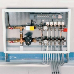
Mixing unit for a warm floor
The use of a warm floor for heating the premises has already ceased to be an innovation. Many are equipped with warm floors, if not the whole house, then separate rooms, for example, a bathroom or living room. Of course, simultaneously with warm floors, other heating devices, for example, are familiar to all radiators, are also used. Warm floors belong to low -temperature heating systems, and heating radiators to high -temperature, therefore, a mandatory element in the underlying system is the mixing node of the warm floor. The main function of this node is mixed, which follows from the name. Why a mixing knot is needed, what it mixed with, what is the principle of its operation, as well as the installation and settings algorithm, we will tell you all this in this article. We also give examples of working schemes for the installation of the mixing unit in the heating circuit and denote the nuances.
- Why do you need a mixing unit for a warm floor
- How the knot of the trunk for a warm floor works
- The scheme of the mixing unit of the warm floor
- Setting a mixing pump unit for a warm floor
Why do you need a mixing unit for a warm floor
It is necessary to immediately clarify that the mixing node is necessary only for the waterproof water system, since the same coolant flows in it as in heating radiators. As a rule, the heating system is organized in this way: one boiler, heating the coolant, the circuit of high -temperature radiators and a circuit or several circuits of a water floor.
The boiler, of course, heats the water to the temperature that is required for high -temperature radiators. Most often this is 95 s, but sometimes radiators are used for a temperature of 85 75 C. According to sanitary standards, the floor surface temperature should not exceed 31 s, this is due to many reasons, and primarily with a comfortable stay on the flooring, so that it is not cold It's not hot. Given the thickness of the floor screed, in which the pipes of the system of the warm floor, as well as the thickness and type of flooring, the temperature of the coolant in the underlying pipes should be 35 55 s and not higher. It is logical to assume that water cannot be directed directly from the boiler to the heating circuit, since its temperature is too high. What to do? How to lower the temperature of the coolant?
It is with the purpose of lowering the temperature of the coolant at the entrance to the warm floor circuit A mixture node for a warm floor is used. It mixes hot coolant and colder heat -coolant of the warm floor. As a result, the average temperature becomes lower, the coolant is supplied to the circuit. All contours of heating in the house work correctly: hot water is supplied in the radiator circuit with a temperature of 95 C, and in the warm floor circuit with a temperature of 55 C.
If you are interested in the question of whether it is possible to do without a mixing unit and in what situations, then we will answer this possible. If heating throughout the house is made using low -temperature circuits, and the heat source heats the coolant only for the heating system to a given temperature, then the mixing nodes can not be used. An example of such a heating system can be the use of an air heat pump. If the heat source heats water not only for warm floors, but also for a shower, the temperature of which is 65 75 C, then the installation of the mixing unit is required.
How the knot of the trunk for a warm floor works
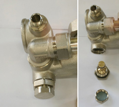
Conventionally, the operation of the mixing unit can be described as follows: the hot coolant reaches the warm floor collector and rests against the safety valve with the thermostat, if its temperature is higher than the required, the valve is triggered and the cold return is supplied, the mixing of hot and cold coolant occurs. As soon as the temperature reaches the required values, the valve is again triggered and the supply of hot coolant. We will consider in more detail the operation of the node below, as it can be organized in two ways.
The collector node for a warm floor serves not only to adjust the temperature of the coolant, but also to ensure its circulation in the circuit. Therefore, the collector node consists of two main elements:
- Safety valvethat we have already talked about. It feeds the heating circuit with a warm heat carrier exactly as much as necessary, controlling the temperature at the entrance.
- Circulation pump, which ensures the movement of water in the circuit of a warm floor with a given speed. This guarantees that the heating of the entire area of \u200b\u200bthe warm floor will be uniform.
In addition to the main elements, the mixing node may include: Bypasswhich protects the node from overloads, drainage and cutting valves and air vents. Therefore, the collector mixing node can be performed in various ways depending on the tasks.
The mixing node is always installed to the contour of the warm floor, but the place of its installation can be different. For example, it can be equipped directly in a room with a warm floor, in a boiler room on the separation of collectors going to a high -temperature contour and a low -temperature circuit. If there are many rooms with warm floors, then the mixing nodes are installed in each room separately or in the nearest collector cabinet.
The main difference in the operation of mixing nodes is that different safety valves can be used in them. The most common are 3 running valves and 2 running valves.
Mixing node with a two -way valve
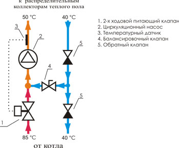
The two -way valve is sometimes also called a power valve. A thermostatic head with a liquid sensor is installed on this valve, which constantly controls the temperature of the coolant entering the warm floor circuit. The head opens and closes the valve, and thus adds or cuts off the supply of hot coolant going from the heating boiler.
It turns out that the mixture of coolants occurs in this way the coolant from the return is constantly supplied, and the hot coolant is supplied only when necessary, i.e. Its feed is regulated by the valve. In this regard, the warm floor never overheats and its life is extended. The two -way valve has a low throughput, due to which the control of the temperature of the coolant occurs smoothly, without sharp jumps.
Most specialists in the installation of warm floors prefer to install a water mixing node with a two -way valve in a warm floor. But there is a restriction of them to establish if a heated area is more than 200 m2.
Flowering node with a three -way valve
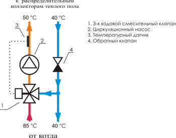
The three -way valve combines the functions of the supply valve and bypass balancing crane. Its main difference is that he mixes a hot coolant inside himself with a cold return. Three -way valves are quite often equipped with servo drives that control thermostatic devices and weather -dependent controllers. Inside such a valve there is a damper, which is located in the zone 90 between the hot coolant supply pipe from the boiler and the return pipe. You can set any median position or with a bias in one of the sides, depending on the necessary ratio of the mixture and hot water mixture.
It is believed that this type of valves is universal and indispensable in heating systems with weather -dependent controllers and simply in large -scale systems with many contours.
The disadvantages of three -way valves should also be indicated. Firstly, the case is not excluded when, according to the signal from the thermostat, the three-way valve opens and will let hot coolant with a temperature of 95 s into the warm floor circuit. Sudden temperature jumps are unacceptable in the operation of warm floors, pipes can burst from excess pressure. Secondly, due to the large throughput of three-way valves, even the minimum displacement in the control of the valve will lead to a significant change in temperature in the circuit.
Why are weather dependent reinforcement used? To change the power of the system warm floor depending on weather conditions. For example, with a sharp decrease in temperature overboard, the room cools faster, which means that the warm floor will not cope with the task of heating the house. In order to increase its effectiveness, it is necessary to increase the temperature of the coolant and the flow rate.
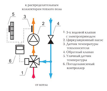
Of course, you can use manual control valves and each time you manually twist the valve with a temperature change. But it is difficult to set the optimal mode in this way. Therefore, valves with automatic control are used. The weather -dependent controller calculates the necessary temperature and controls the valve very smoothly. The entire spectrum 90 is divided into 20 sections of 4.5. The controller checks the temperature every 20 seconds, and if the actual temperature of the coolant supplied to the warm floor does not correspond to the calculated one, then the controller turns the valve by 4.5 in the required direction.
Also, the controller allows you to save on energy. If all the tenants are absent, it reduces the temperature of the house and supports it within the given value.
The scheme of the mixing unit of the warm floor
Below are the most common schemes of mixing nodes, but in fact there are much more. Mixing coolants can be produced both to collectors and directly on each divert of collector groups. At the same time, each collector group will need to be equipped with its thermostats, consumables and valves.
Schemes of mixing nodes (this is how the warm floor assembly looks like assembly):
- Valtec's mixture unit for one circuit (up to 20 m2.)

- Valtec's mixture unit for one circuit (up to 20 m2.) With automatic adjustment

- Valtec warm floor collector for 2 - 4 contours (20-60 m2.)

- Valtec's mixture unit for 2 - 4 contours (20-60 m2.) With automatic adjustment

- ValTec warm floor collector for 3-12 contours (30-150 m2.)

- Balancing valve of the secondary circuit.
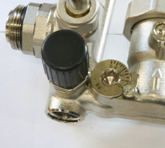
Using the balancing valve, the ratio of the costs of hot coolant and cold coolant from the return is adjusted. In fact, the temperature in the circuit of the warm floor is set. The valve rotation is performed using a hexagonal key. In order not to accidentally shift the valve position, it is fixed using a clamping screw. Also on the valve there is a scale for the valve capacity of the valve from 0 to 5 m3/h.
- Balancing-refinery valve of the radiator circuit.
This valve is used for a bundle of a mixing unit with all other elements of the system. The valve also rotates using a hexagonal key.
- Roll -out valve.

This is a safety valve, the task of which is to protect the pump from the mode in which the coolant duct stops through it. This valve is triggered if the pressure in the system is reduced to a given value. The value is set by the handle.
Installation schemes of mixing nodes:

The schemes also differ depending on whether a single -pipe heating system or two -pipe. For example, with a one -pipe bypass, the bypass is always in an open position, so that part of the hot coolant can always follow the direction of the radiators (photo below).

In the two -pipe heating system, the bypass is closed, since it is not necessary (photo below).

Please note that the collector group of a warm floor does not have to be installed to the radiator circuit. If the area of \u200b\u200bthe house is not too large and the drop in the temperature of the coolant is not too large, then the collector with a mixing node can be installed on the return of the radiator circuit.
Setting a mixing pump unit for a warm floor
After installing the mixing unit according to the selected scheme, its operation must be adjusted. The installation itself is quite simple, it is only necessary to connect the pipes to each other, but the setting will require clarification.
- Thermogram or servo drive must be removed so that they do not affect the knot during the settings.

- The bypass valve should be set to the maximum position 0.6 bar. If the valve accidentally works during the settings, then the result will be incorrect. Therefore, it should be established in a position in which it will not work.

- Next, you should calculate the position of the balancing valve of the circuit of the warm floor. Further, for convenience, we will indicate 1 radiator circuit, 2 circuit of a warm floor.
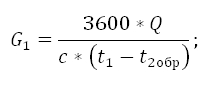
Required capacity of a balancing valve calculated by the formula:
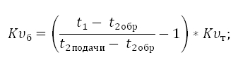
Where,
t1the temperature of the coolant in the supply pipe of the radiator circuit (high -temperature circuit);
t2DACHThe temperature of the coolant in the supply pipe of the circuit of the warm floor;
t2obr The temperature of the coolant in the pipe of the return circuit of the warm floor;
Ktcoefficient \u003d 0.9.
Example of calculation:
Accept that T1 \u003d 95 C, T2 sunset \u003d 45 C, T2obr \u003d 35 C. Substitute the values \u200b\u200bin the formula:
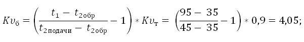
The resulting value of KB is set on the balance sheet valve.
- Next, you need to configure the pump.
To set up the pump, it is necessary to calculate the flow rate of the coolant in the warm floor circuit along with the collector and pressure loss in the circuit after the mixing unit.
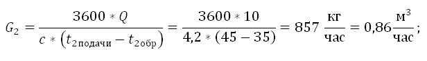
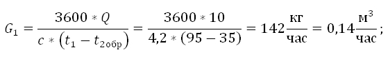
The flow rate of the coolant in the warm floor circuit calculated by the formula:
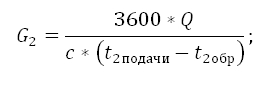
Where,
G2 the consumption of the coolant in the circuit of the warm floor in the secondary circuit;
Q. the amount of thermal capacities of all devices connected after the mixing unit;
c. The heat capacity of the coolant. If the coolant is water, then C \u003d 4.2 kJ/(kg*s);
t2DACHand t2obrThe temperature of the coolant in the warm floor circuit: on the feed pipe and in the return;
Example of calculation:
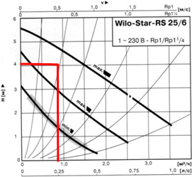
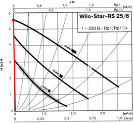
In order to calculate the pressure loss in the circuit of the warm floor, it is necessary to perform a hydraulic calculation. For convenience, you can use the free program for calculations on the manufacturer’s site of the mixing units, for example, the Valtec.prg program.
According to the charts below, it is necessary to determine the speed of the pump.

First, we mark the point that corresponds to the flow and pressure of the pump. The curve, which is above the obtained point, will correspond to the speed of the pump. The resulting value of the flow \u003d 0.86 m3/h, the pressure of the pump \u003d 4.05 m V.st.
Pressure losses in the contours after the mixing nodetake with a margin of 1 m V.st.
PN \u003d ps + 1 \u003d 4,05 + 1 m V.st.
Pump schedule:
If for some reason the pump cannot be calculated, you can skip this setting stage. In this case, it is necessary to put the pump in a minimum position. If in the future, in the process of balancing the system it turns out that there is not enough speed, then just put the pump at high speed.
- The next stage must be performed by the balancing of the veins of the warm floor.
First, it is necessary to close the balance sheet valve of the radiator (primary) circuit. We throw off the lid from the valve and turn it until it stops clockwise with a hexagonal key.
The branches of the warm floor circuit are balanced using balancing valves. If after the mixing unit is only one branch of one circuit of a warm floor, then nothing needs to be balanced.

How is balancing:
- Balancing regulators must be opened to the maximum;
- On that branch, the deviation of the consumption of which is the maximum (actual consumption from the design), the valve must be closed to the required size.
- All branches of the warm floor are adjusted in the same way.
- If the consumption is lost after balancing the branches, it is necessary to adjust it again.
- If it is not possible to set the required consumption even with open valves, the pump must be switched to higher speed.
- Next, it is necessary to link the mixing unit for a warm floor with other heating devices.
First of all, we open the balancing-recover valve of the radiator circuit, which we closed at the very beginning. It is necessary to open it to the position that will ensure the required flow rate of the coolant.

The flow rate of the coolant can be controlled using flow meters. The control option for a warm floor is also possible.
Carboniferous consumption in the radiator circuit calculated by the formula:
All values \u200b\u200bto us are already known from previous calculations, so we expect:
- Now we set up the bypass valve.
We set the valve pressure, its value should be less by 5 10 % of the maximum pump pressure at a given speed. The maximum value of the pump pressure must be determined by the characterization of the pump.

The bypass valve of the pump should be opened only in the situation where the pump works for pressure injection, and there is practically no water flow.
The chart below shows how the value of the bypass valve is determined.
In the absence of water movement in the pipeline at the first speed, the pump pressure 3.05 m V.st. or 0.3 bar. At an average speed of 4.5 m V.st. or 0.44 bar, at the maximum 5.5 m V.st. or 0.54 bar.
We install a value of 0.54 5% \u003d 0.51 bar on the bypass valve.
- We check the correctness of the mixing unit.
It is necessary to verify the uniformity of warming up the twigs of the warm floor and the correct temperature ratio in the contours.
The following equality should be performed:
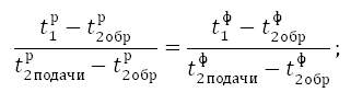
Index R means that the value is calculated and the index f - Actual.
If the equality is not executed, then the balance sheet valve of the radiator circuit should be closed on the turnover and again remove the readings and perform calculations.
If the equality is executed, then the mixing node works correctly, it is necessary to install the thermogram or servo drive in the place, put the protective caps on all the elements that require this, and tighten the screw of the balancing valve.
Example of calculation:
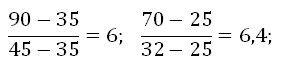
The deviation in the values \u200b\u200bis 6.6 %, this is less than 10 %. This means that the mixing node is correctly configured, you can install the thermogram and protective caps and proceed to the operation of the heating circuit.
The mixing heating unit is installed in a collector cabinet, which is usually located in a room with warm floors and next to it. But you can also install it next to the heating boiler, if the distance to the warm floor is not too large. All elements of the mixing unit can be assembled independently, or you can purchase a finished product. It all depends on your skills and knowledge.
![]()
StrPort construction portal 2011-2018. Articles about repair, construction, building materials.
Copying information from the site is possible only with permission of the editorial office Or indicating a direct link to the source. Legal justification